
August 1983: the first ad of the FT-ONE that appeared on an Italian (departed) amateur radio magazine. I was 15 years old and without experience (I would have become a CBer the year after) but still enthusiast, and I fell in love with this radio: it was large, full of controls, meters, displays and lights! Obviously unreachable for my pocket money...
Passing the years and coming in the "world of radio" and electronics, I saved the idea that this transceiver had something more, despite the technological progress and the coming of new "flagships"!
In 2015 - 32 years later - my dream came true and I became owner of this beautiful radio, coming from Tuscany.
It is well known, to a FT-ONE user, that the fan is 1) always running when the radio is powered on and 2) noisy!
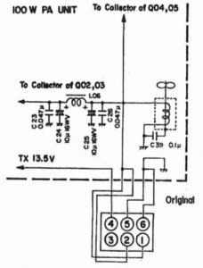
I think that the owners claimed about that, if the company decided to develop a mod kit, for limiting the fan operation to the transmission and depending on the PA temperature. The picture at the side, taken from the instruction sheet of the kit, shows that the fan motor is originally connected to the 13.5 V rail of the PA (terminals #1 and #2 of the connector).
The solution was incredibly simple: a diode and a thermal switch.
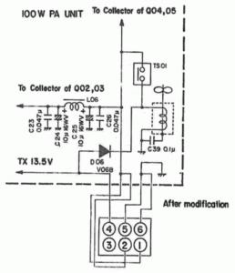
In the "after modification" schematic, the new diode (D06) takes power from the "TX 13.5V" rail of the PA (active during transmission, for driving the bias circuits of the amplifier), and the thermal switch (TS01) closes on the 13.5 V rail when the temperature rises over a certain value, nothing else matters.
The picture, taken form the instruction sheet, shows the inside of the PA unit and the mods. Unfortunately the change of state temperatures of the thermal switch are unknown.
So, before starting on my FT-ONE, I decided to look for informations, in order to avoid the risk of stressing the transistors: e.g. taking a look to other RTX equipment.
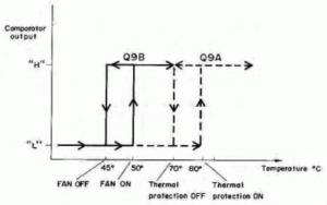
The Kenwood TS-440S is equipped with an electronic thermal switch circuit that controls the fan (and the protection), and its service manual explains its operation - see the state diagram.
The power transistors are different - a push-pull of two 2SC2879 in the TS-440S - but they have the same junction temperature (175 °C) of the 2SC2290 used in the FT-ONE.
The two radios share a similar thermal management system. I decided, therefore, to adopt the same temperature setpoints for the fan operation.
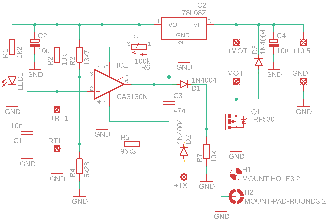
I decided the electronic solution for my FT-ONE, too: a negative temperature coefficient thermistor (NTC), a Schmitt trigger based on an operational amplifier, and a power MOSFET sized for the fan motor.
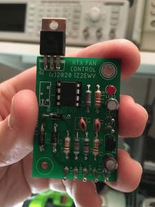
The circuit that I designed - and that I hold among my fingers - will activate the fan over 50 °C and shut off it under 45 °C.
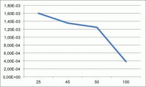
I used the current I to verify the dissipation of the NTC at the interested temperatures (see diagram, printed, as well as the values in the table, from an Excel spreadsheet). According to its data sheet, the component may tolerate 150 mW at 25 °C: at the same temperature corresponds the maximum power dissipated by my circuit (1.6 mW).
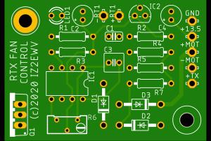
And this is the component side of the circuit, which I drew with the Eagle software. I uploaded the Gerber file to a PCB manufacturer, who sent me 5 pieces for a modest price. On request, I can sell to the interested OMs the PCB and some components (NTC, R3-R4-R5 network, CA3130).
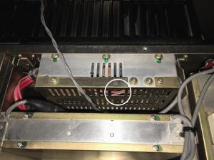
I don't know what it's for, but the little window on the PA cover, circled in the picture, is perfect to let the few wires reach the fan control circuit: the positive "13.5V" supply for the PA, the positive "TX 13.5V" rail, the fan motor and the NTC. The metal enclosure is the negative to ground.
On the right hand side of that window there are two housings for standoffs, not used in my FT-ONE, which I decided to use for my fan control circuit.
The only modification needed was a third hole, which I drilled near the right edge (see picture), that will act as ground connection for my circuit, too.
Among the three standoffs, shown mounted on the PA cover, the above one is insulated, because the MOSFET, which is at positive voltage, will be placed over it.
The following pictures show the wiring and mounting steps of the circuit. The reinsertion of the PA inside the FT-ONE requires care, but it was successful as well.
, TX 13.5V (white) and fan motor (grey cable)")

